



Crimping Process Requirements and Installation of Cold-Pressed Terminals: A Professional Guide
The Foundation: Understanding the Crimp and Its Critical Importance
A proper crimp is more than just squeezing a terminal onto a wire. It is a metallurgical process designed to forge a permanent, gas-tight union. The terminal's copper barrel is mechanically deformed around the wire strands under immense, calibrated pressure. This process:
-
Displaces surface oxides, allowing for pure metal-to-metal contact.
-
Cold-welds the strands together and to the barrel wall.
-
Creates a connection that is often more reliable and consistent than the wire itself.
A failed or substandard crimp is a primary point of system failure, leading to increased resistance, localized overheating, energy loss, and potential safety hazards. Adhering to stringent process requirements is therefore non-negotiable.
Phase 1: Pre-Installation Requirements and Preparation
1. Component Verification & Selection:
-
Terminal-to-Wire Match: The terminal barrel must be precisely matched to the wire's cross-sectional area (AWG or mm²). Using an oversized barrel results in insufficient compression; an undersized barrel can crush and damage conductors. Use manufacturer-specified compatibility charts.
-
Material Quality: Ensure terminals are made from high-conductivity copper alloy with appropriate plating (e.g., tin for general use, silver for high temperature). Gaopeng terminals are manufactured with these specifications to ensure optimal performance.
-
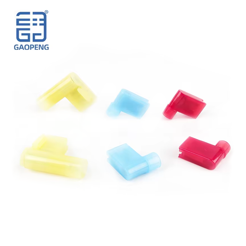
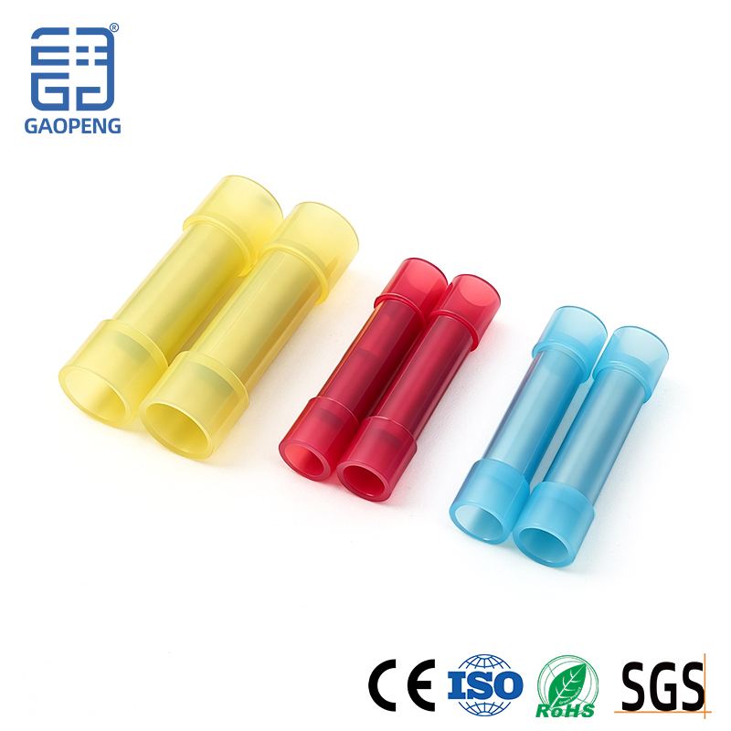
Insulation Type: Select the correct insulation material (Nylon, PVC) and rating for the application environment (temperature, chemical exposure, flame retardancy).
2. Tooling Calibration and Selection:
-
The Right Tool for the Job: Never use non-dedicated tools like pliers. A ratcheting crimp tool with a matched, color-coded die set is mandatory for consistent results. The ratchet ensures a complete crimp cycle is achieved every time before release, preventing under-crimping.
-
Die-to-Terminal Compatibility: The die set must be certified for the specific terminal type and size being used. Cross-brand compatibility is not guaranteed. Using the wrong die profile will create a structurally weak or electrically poor connection.
3. Wire Preparation:
-
Stripping Length: Strip the wire insulation to the exact length specified for the terminal. The goal is for all strands to sit fully within the barrel, with the insulation ending precisely at the barrel's mouth—no exposed wire behind the crimp, and no insulation trapped inside it.
-
Strand Integrity: Trim any frayed or uneven strands. For multi-stranded wire, gently twisting the strands ensures they enter the barrel neatly as a unified bundle.
Phase 2: The Critical Crimping Process: A Step-by-Step Protocol
Step 1: Insertion
Insert the prepared wire end fully into the terminal barrel until it reaches a positive stop or the insulation butts firmly against the barrel's entrance. Visually confirm full insertion.
Step 2: Tool Placement
Place the terminal into the correctly sized die nest of the crimping tool. The terminal should be oriented as specified (often with the seam of the barrel aligned with a tool marker). Ensure the tool jaws are clean and undamaged.
Step 3: Crimp Execution
Apply firm, smooth pressure to the tool handles. Allow the ratchet mechanism to complete its full cycle automatically. Do not interrupt the crimp. You should hear/feel a definitive click upon completion. The tool will only release after applying the pre-set, calibrated pressure.
Step 4: The Anatomy of a Perfect Crimp
A quality crimp has distinct visual and tactile characteristics:
-
Indentation: The crimped section should show symmetrical, clean indentations from the die.
-
"Bell-Mouth" Entry: A gentle flair at the insulation end of the barrel provides essential strain relief, preventing bending stress from concentrating at a sharp edge.
-
Wire Position: The insulation should end exactly at the barrel's beginning, with no gaps or bulging.
Phase 3: Post-Crimp Inspection and Quality Control
Visual and mechanical inspection is mandatory for critical applications and a best practice for all.
-
Visual Inspection: Check for symmetry, proper indentation depth, correct wire position, and absence of cracks or splits in the barrel or insulation.
-
Tug Test: Apply a firm, axial pull (approx. 15-20 lbs of force for typical control wiring) to the wire. The wire should not pull out of the terminal or show any movement within the crimp. The insulation/grip area should provide strain relief.
-
Cross-Sectional Analysis (for high-reliability sectors): In aerospace or automotive, random samples are cross-sectioned and measured under microscope to verify compression depth, strand fill, and the absence of voids, ensuring compliance with industry standards like IPC/WHMA-A-620.
Phase 4: Final Installation and Connection Best Practices
1. Routing and Handling:
Route wired terminals neatly, avoiding sharp bends immediately at the crimp point. Use Cable Ties and ducting to manage bundles, preventing stress on individual connections.
2. Connection to the Point:
-
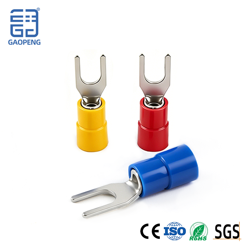
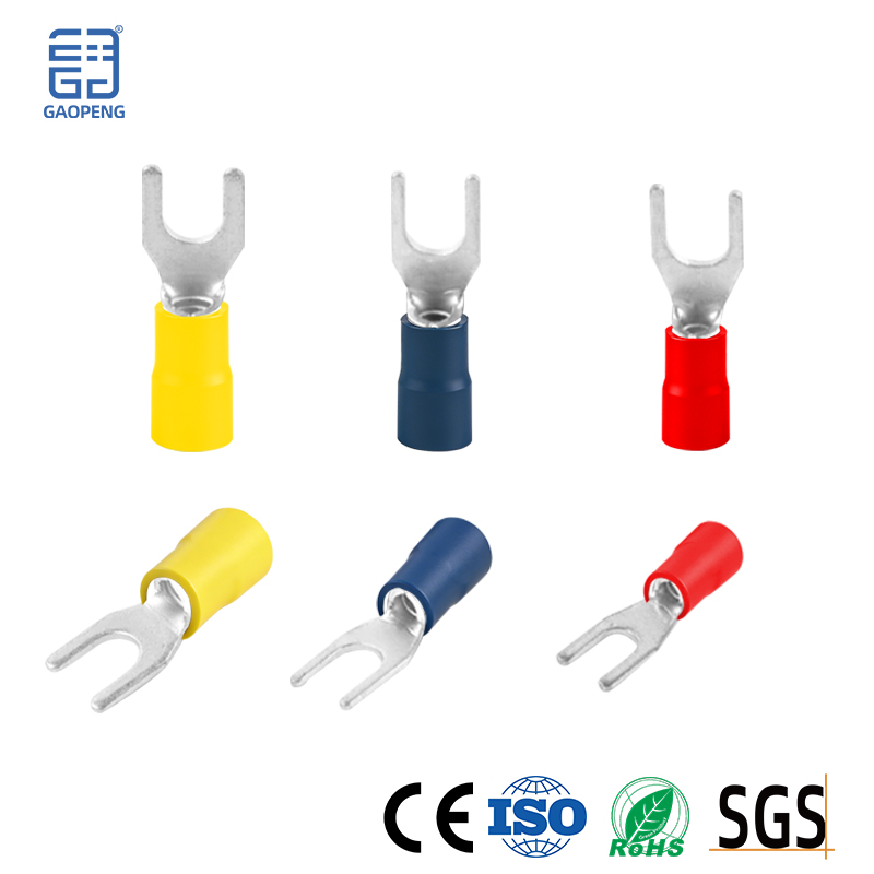
For Stud/Rail Connections (Ring/Spade Terminals): Ensure the terminal sits flat against the mounting surface. Use a properly sized flat washer and split lock washer (if specified) under the nut. Apply manufacturer-recommended torque to the nut to ensure a solid electrical interface without damaging the terminal.
-
For Plug/Receptacle Connections: Ensure the terminal is fully seated and locked into its housing connector with an audible/ tactile click. Perform a secondary check to confirm engagement.
3. Environmental Protection:
In harsh environments (moisture, chemicals), apply additional protection such as heat-shrink tubing with adhesive lining over the crimp and wire junction to seal against corrosion and ingress.
Common Pitfalls and How to Avoid Them
-
Under-Crimping: Caused by using the wrong tool, wrong die, or interrupting the crimp cycle. Results in high resistance and wire pull-out.
-
Over-Crimping: Excessive force can crack the barrel, cut strands, or weaken the metal, leading to premature failure.
-
Improper Strip Length: Insulation in the crimp zone increases resistance; too much bare wire exposes a hazard and reduces mechanical strength.
-
Using Ferrules on Stranded Wire for Screw Terminals: This is a related best practice. Always crimp an insulated ferrule onto stranded wire before inserting it into a screw-clamp terminal block. This prevents strand splay and ensures a perfect, solid connection.
Conclusion: The Art and Science of a Reliable Connection
The crimping of cold-pressed terminals is a disciplined fusion of material science, precision tooling, and meticulous procedure. There is no room for approximation. Each step—from selection and preparation to crimping, inspection, and final installation—is a critical link in the chain of electrical reliability.
At Yueqing Gaopeng Electric Co., Ltd., we provide the foundational element: precision-engineered terminals designed for optimal performance within a professional crimping process. We advocate for and support industry best practices because we understand that our customers' success—and the safety of their electrical systems—depends on the integrity of every single connection.
Build with Precision. Install with Confidence. Trust Gaopeng.
For detailed technical specifications, compatibility charts, and support on implementing a quality crimping process in your operations, contact our engineering team today.