



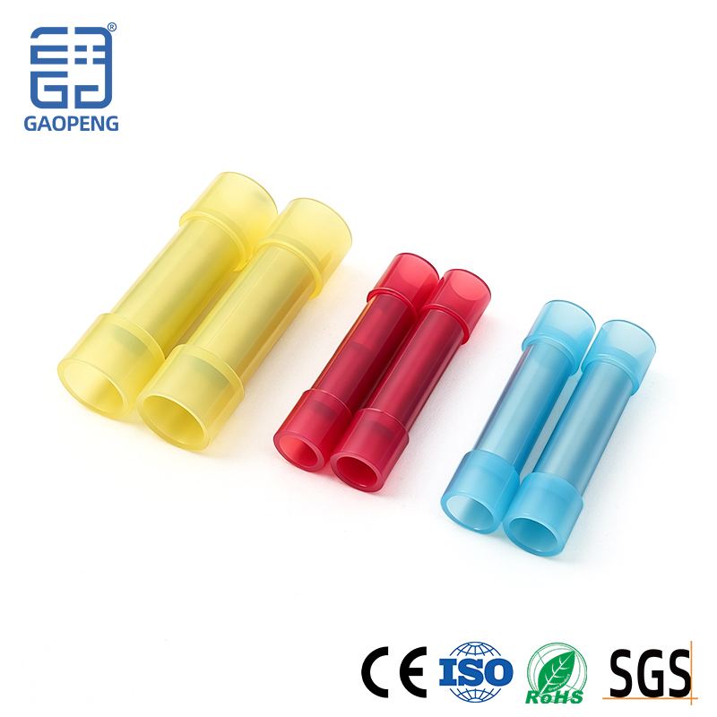
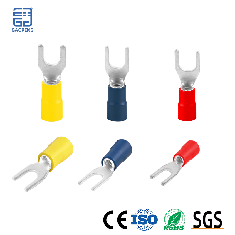
How to Use Insulated Crimp Connector
Tools and materials required
Professional crimping pliers (the most critical!) )
Never use regular pliers or vises! This will lead to weak crimping and false joints, which will cause heat and even fire in the future.
Crimping pliers should have crimping notches that match the terminal size (usually marked with a wire cross-section, e.g., 0.5-1.0mm²). It is best to choose ratchet crimpers, which will ensure that they are automatically released after each press is in place, ensuring consistent crimping quality. Insulated Crimp Terminals (choose the model that matches the cross-sectional area of the wire)
Standard Operating Procedure (Ring Terminal as an Example)
Step 1: Preparation
Power out! Before connecting any circuit, it is important to make sure that the circuit in question is completely de-energized.
Choose the Right Terminals: Check the nominal cross-sectional area of the metal sleeve portion of the terminal (e.g., 22-10 AWG or 0.5-6mm²) to ensure it completely covers your wire size. It is better to be big than small.
Choose the Right Crimping Die: Locate the crimping notch on the crimping pliers that corresponds to the terminal size.
Step 2: Strip the wires
Using wire strippers, peel off the insulating skin at the end of the wire.
The peel length (L) is crucial: it should be exactly equal to the length of the terminal metal sleeve. It is usually a little shorter than the insulating sleeve, ensuring that all copper wires are wrapped around the sleeve and that the insulating skin is protected by the end of the insulating sleeve of the terminals.
Too long: exposed copper wire, there is a risk of short circuit.
Too short: Some copper wires are not pressed, and the connection strength is insufficient.
Step 3: Insert the wire
Insert all the stripped wires into the metal sleeve of the terminal until the front end of the wire insulation skin just touches the end of the sleeve. Check for scattered copper wires.
Step 4: Crimping
Place the terminals in the correct bayonet of the crimping pliers, making sure that: the metal sleeve section is in the crimping slot. Do not put the insulating sleeve into the crimping groove, otherwise it will be crushed. Usually the crimping pliers have a "C" shaped mark, and the crimping point should be opposite the "seam" of the sleeve. Firmly grip the crimping pliers handle until the ratchet mechanism automatically releases (if using ratchet pliers). You will hear a "click".
Once the correct crimping is done: the metal sleeve should be evenly pressed and deformed, wrapping around the wire. The wire should be firmly fixed and will not be pulled out if pulled hard. The insulating sleeve part should be intact.
Step 5: Check and test
Visual inspection: The crimping site should be evenly deformed without cracking. The wires are not exposed.
Pull test: Apply appropriate force (non-destructive) to pull the wires and terminals with your hands to see if they are loose. NOTE: Do not use brute force on small terminals.
Electrical test (after final installation): Use a multimeter conduction file to check if the connection points are well conducted, and the resistance should be close to zero. After the actual power is on, you can also use an infrared thermometer to check whether there is an abnormal temperature rise at the connection point.