A 12V wire gauge chart needs both current and circuit length to give a useful result. The chart below selects a conductor for an illustrative 3% wire-only voltage-drop target at 12.0 V. It does not establish the cable’s safe ampacity, fuse size or suitability for a particular installation.
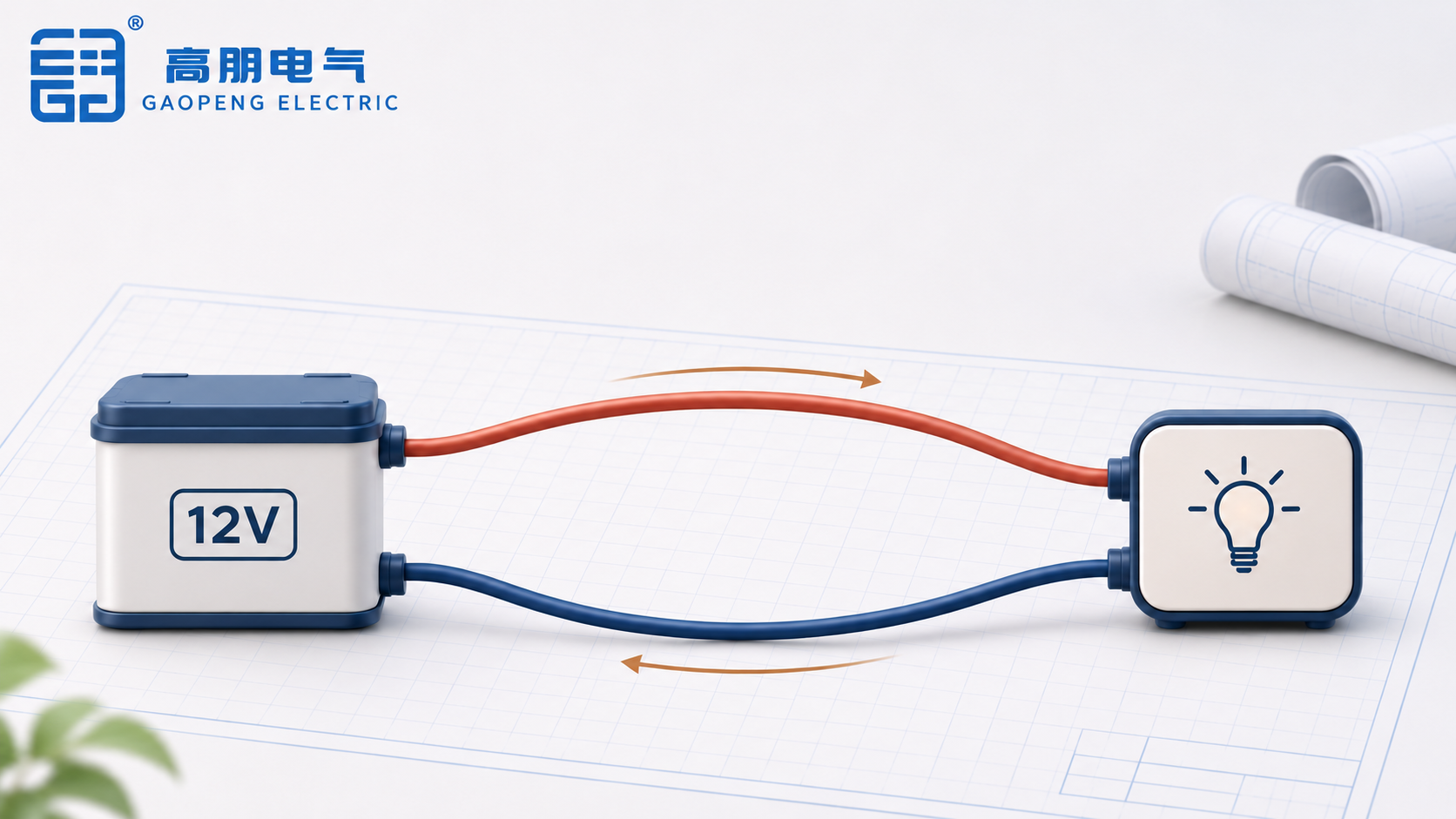
Read the distance columns as the one-way route from source to load. The calculation includes an equal-length copper return conductor, so a 10 ft route means 20 ft of conductor in the circuit. A chassis return, unequal conductors or additional connections require their own resistance assessment.
12V wire gauge chart: a stated 3% voltage-drop example
Each cell gives the thinnest conductor that meets the target within this tested set: 16, 14, 12, 10, 8, 6 and 4 AWG. Intermediate gauges were not tested. A lower AWG number means a larger nominal conductor. These are calculated reference values, not measurements of a supplied cable.
| Load current | 5 ft one way | 10 ft one way | 15 ft one way | 20 ft one way |
|---|---|---|---|---|
| 5 A | 16 | 14 | 12 | 12 |
| 10 A | 14 | 12 | 10 | 8 |
| 15 A | 12 | 10 | 8 | 6 |
| 20 A | 12 | 8 | 6 | 6 |
Calculation conditions: nominal 12.0 V; maximum wire-only drop 0.36 V; standard copper resistivity 0.017241 Ω·mm²/m at 20°C; equal conductor sections and route lengths in both directions. Connector resistance, switches, fuse holders, temperature rise and cable-specific construction are excluded. The 3% target is an example chosen for this chart, not a universal legal requirement.
The calculation uses nominal AWG metal area derived from the published diameter formula. Finished stranded-cable outside diameter includes insulation and is not that metal diameter. Before ordering, compare the result with the actual cable manufacturer’s resistance and current-rating data.
Count the return path before calculating the drop
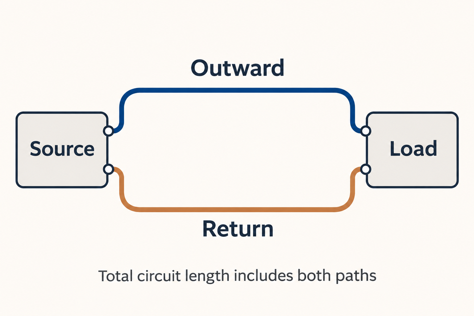
For equal outward and return conductors, wire-only voltage drop is:
Voltage drop = current × resistance per metre × 2 × one-way length in metres.
Consider a 10 A load located 10 ft from its source. The conductor path totals 20 ft, or 6.096 m. Nominal 12 AWG copper has an area of approximately 3.31 mm². With the reference resistivity above, its resistance is approximately 0.00521 Ω/m at 20°C.
The calculated drop is 10 × 0.00521 × 6.096, approximately 0.318 V, or 2.65% of 12.0 V. It passes the example’s 0.36 V wire-only target. Under the same assumptions, 14 AWG drops approximately 0.505 V and fails that target. This comparison explains the 12 AWG cell; it does not approve a specific cable or finished circuit.
Connection losses would consume additional voltage. If the equipment needs a minimum operating voltage, assess that requirement against the source’s actual voltage range and the losses of the complete path. A calculation based on a nominal battery label alone cannot establish the voltage available at the load.
Check ampacity separately from voltage drop
Voltage drop addresses the voltage lost along a resistance. Ampacity addresses the permitted current under defined installation conditions. Passing one check does not establish the other. The designer must also consider insulation rating, ambient temperature, bundling, routing and equipment limitations.
For example, a short route can produce a small calculated drop even when the selected cable is unsuitable for the installation. Increasing route length can require a larger conductor for voltage drop even when a smaller conductor would otherwise satisfy the current requirement.
Published charts can disagree because they answer different questions. One manufacturer reference below uses a 10% drop basis at 100°F in free air. It is not interchangeable with this 3%, 20°C calculation. Compare assumptions before comparing gauge recommendations, particularly when a chart labels its distance simply “length.”
Higher conductor temperature changes resistance. Actual stranded-cable data can also differ from this nominal geometric reference. Use the finished cable’s applicable data and the responsible designer’s requirements when turning a chart result into a purchase specification.
Carry the selected conductor through to the connector specification
Once the cable requirement is settled, the connector needs its own fit check. Specify conductor metal, section or AWG, strand construction and insulation outside diameter. A connector selected before the cable is enlarged for voltage drop may no longer match the approved wire.
Gaopeng’s heat-shrink butt connectors provide a copper-barrel, adhesive-lined sleeve option to evaluate for a specified splice. Confirm the fit of both wire ends, the applicable crimping instructions and the required sealing conditions. The product family name does not assign an ampacity to the complete 12V circuit.
For a quotation, send the final wire designation, both insulation diameters, operating environment and quantity by connector size. Ask for the exact proposed reference and supporting dimensions. That gives the buyer a connector proposal tied to the selected cable rather than an ambiguous “12V connector” description.