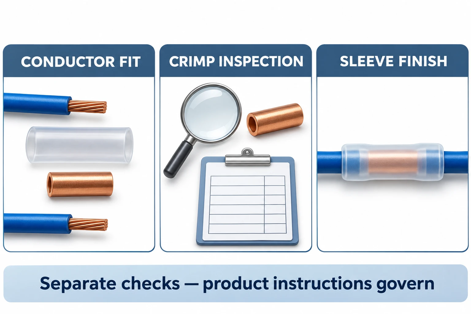
When deciding how to splice a wire, select a connector documented for both conductors and obtain its installation instructions. For an insulated crimp butt splice, the sequence is to establish isolation, prepare the wire ends, insert and crimp them with the specified tooling, inspect the crimp, then finish the heat-shrink sleeve as instructed.
This guide concerns disconnected low-voltage copper bench or harness wiring. It does not provide a procedure for building mains, energized equipment, high-voltage batteries or safety-critical vehicle circuits. If the circuit or its isolation is uncertain, stop and use a qualified person and the equipment-specific procedure.
How to splice a wire: establish isolation first
Begin with the applicable energy-isolation procedure, not the stripping tool. A switch being off is not, by itself, proof that a conductor is safe to handle.
For US workplaces within its scope, OSHA 1910.333 addresses disconnection from electrical energy sources, lockout/tagout conditions and verification of the deenergized state by a qualified person. Its verification requirements include possible backfeed. These are workplace safety requirements, not approval of a connector or a complete isolation procedure for every device.
For the bench work discussed here, keep the wiring disconnected from its supply throughout preparation and inspection. Resolve stored energy, unintended reconnection and any uncertain circuit identity through the applicable equipment and workplace procedure before touching exposed conductors.
Match the connector to both wire ends
Identify the conductor material, size and construction at each end. Do not assume that a connector suitable for one side also accepts the other, especially when the wires differ. Obtain the selected part’s wire acceptance, preparation and tooling instructions before starting.
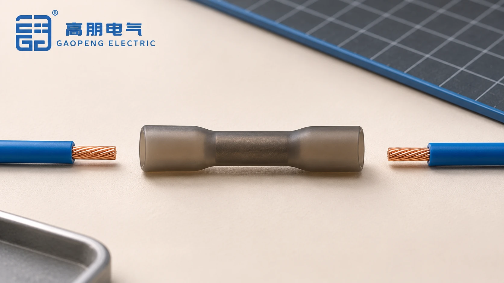
Gaopeng’s heat-shrink butt connector listing describes a copper contact and an adhesive-lined, dual-wall polyolefin sleeve. It asks buyers to specify both conductors, barrel and crimp-profile requirements, and the required sealing conditions. The listing does not establish a single strip length or heating schedule for every variant.
Choose the exact reference and confirm those missing instructions. A connector’s color, sleeve appearance or resemblance to another manufacturer’s part cannot supply its installation settings. The barrel connection and the finished insulation or seal are separate requirements.
Prepare, insert and crimp against the actual instruction
Use the following checkpoints with the selected connector’s instructions. The required dimensions, tool, die and acceptance criteria must come from that documented combination.
- 1. Prepare each end. Strip the length specified for the part and wire. Inspect for visible conductor damage, missing strands and insulation remnants. Resolve damage before inserting the wire; do not use a generic strip length copied from a different connector.
- 2. Establish conductor engagement. Insert each prepared end to the position required by the connector instruction. Confirm that the intended conductor, rather than insulation, occupies the required contact area. Do not fold or double a conductor to compensate for an unconfirmed fit.
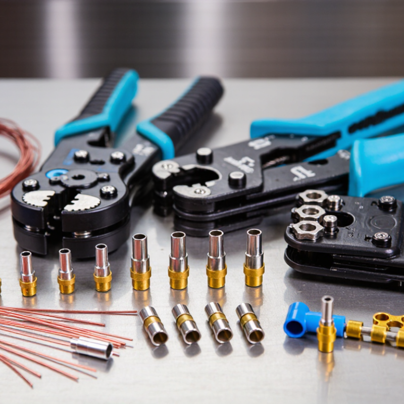
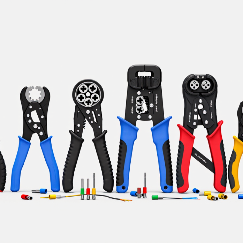
- 3. Apply the specified crimp. Use the identified tool and appropriate die position. Follow the instruction for locating the barrel and completing each end. A general-purpose pair of pliers is not a substitute for an identified crimp profile.
- 4. Inspect before finishing. Check crimp location and conductor engagement against the acceptance instruction while the joint can still be assessed. Keep an uncertain or visibly damaged connection out of service.
Molex’s tooling specification for its named Perma-Seal parts illustrates why the exact instructions matter: it specifies the applicable terminals, preparation details, crimp position and inspection, including a separate arrangement for the second end of a butt splice. Those tool-specific details do not become instructions for a Gaopeng connector.
Finish the sleeve without hiding an unresolved crimp
The heat-shrink sleeve finishes the insulation and, for an appropriately specified adhesive-lined product, forms part of the sealing system. It does not replace the mechanical crimp. Resolve the crimp inspection before applying the finishing process.
Follow the selected product’s heating method, limits and finish indicators, including any required cooling stage. Keep the surrounding wire insulation and equipment within their permitted conditions. If the method or material compatibility is unknown, obtain the instruction rather than estimating a heat setting or exposure time.
As a product-specific example, 3M’s currently hosted, November 2010 MH-series butt-connector datasheet describes a barrel crimp followed by heat-gun shrinking to its stated adhesive finish indicator. Molex’s Perma-Seal datasheet separately explains the role of hot-melt adhesive during shrinking. Neither document verifies a heating setting or sealing result for a Gaopeng part.
After finishing, inspect the sleeve and wire entry against the applicable criteria. A smooth exterior alone cannot prove that the hidden conductor engagement, crimp or environmental seal meets the requirement.
Keep a record before releasing the assembly
Record both wire references, the connector part, tool and die, instruction revision, and the checks performed. Keep any required electrical, mechanical or sealing test results with that record. Use the specified test method and acceptance criteria; do not invent a universal pull force or treat a simple continuity indication as proof of all connection properties.
For example, if the crimp location has been inspected but the sleeve’s required finish indicator is not known, record the finishing check as unresolved. Heating until the joint merely looks neat would not close that gap. Obtain the correct instruction and resolve the assembly under the applicable repair or acceptance process.
Release and reconnection should follow the equipment or project procedure after all required checks are satisfied. An unresolved conductor fit, damaged sleeve or missing acceptance requirement is a reason to stop, not a condition to conceal with more tubing or tape.
References
OSHA — 1910.333 electrical work practices
Molex — ATS-6400182HM, Revision D, October 17, 2025
Molex — Perma-Seal datasheet, Revision 2, October 2023
3M — MH18BC, MH14BC and MH10BC datasheet, November 2010