Terminal block types describe several different choices. DIN-rail and PCB labels describe mounting formats. Screw, spring and push-in labels describe wire-connection methods. Circuit arrangement adds another question: which positions connect electrically? A useful specification records these fields separately instead of treating every type name as a competing product category.
For a buyer replacing an H-type screw strip, the starting point is the existing connection layout and installation envelope. A familiar outline or matching pole count leaves important questions unanswered. The selected part still needs documented conductor compatibility, electrical ratings and installation requirements.
Read terminal block types as overlapping labels
A PCB terminal block can use more than one wire-connection technology. Likewise, DIN-rail families can include screw, spring and push-in variants. Asking whether a block is “DIN rail or screw” mixes two independent descriptions. Buyers should ask where the block mounts, then how it holds the conductor.
The third field is circuit arrangement. A purchasing record should identify the connections required between wire-entry positions. A row of openings does not provide that information by itself. Buyers should request the connection diagram rather than infer a common electrical connection from the number of positions.
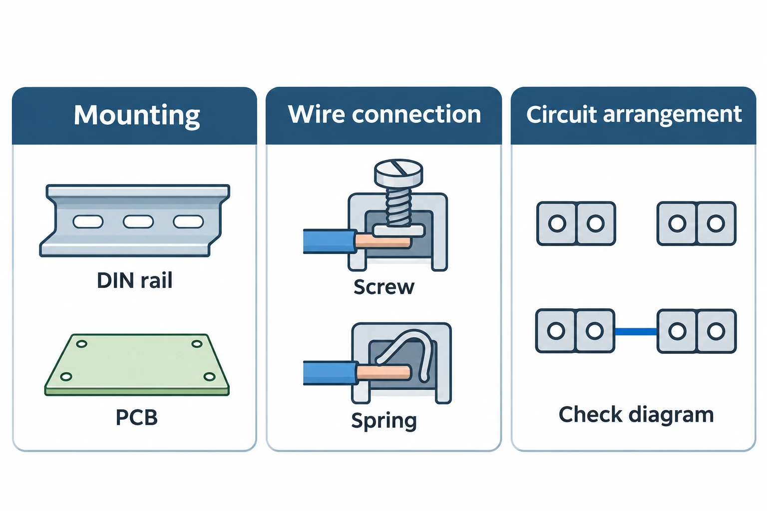
This distinction also improves searches. “PCB screw terminal block” combines mounting and connection information. “Terminal strip” alone leaves more choices open. Adding the required circuit layout and dimensional drawing gives the supplier a much clearer basis for identifying a candidate.
Compare the wire-connection method within the selected family
Screw and spring connection describe different retention mechanisms. Push-in appears within manufacturers’ spring-connection offerings, so a catalog may use both terms at different levels. The exact product instructions determine conductor preparation and insertion requirements. A broad family name does not establish them.
For each candidate, the buyer should ask which conductor sizes and constructions the terminal accepts. The answer needs to distinguish solid, stranded and any specified prepared conductor ends. Neither a screw connection nor a spring connection establishes a universal ferrule requirement.
A comparison should also include the information the assembly team needs: access to the connection, the permitted wire-entry arrangement and the selected model’s installation document. These requirements can rule out a candidate even when its mounting description matches. Claims about maintenance, vibration performance or installation speed need evidence for the particular part and application; the connection label alone is insufficient.
Keep mounting dimensions and circuit layout explicit
The mounting description narrows the search, but a drawing resolves fit. For a strip, the relevant record should show the overall envelope, fixing arrangement and wire-entry layout. For a PCB or rail-mounted candidate, the corresponding mounting details must match the equipment design. These are different drawing checks, not interchangeable uses of the same type label.
The circuit record should travel with that drawing. Buyers can identify each required connection by the equipment’s own wiring references, then ask the supplier to confirm the proposed arrangement. Pole count and electrical connections belong in separate fields. This prevents a replacement discussion from ending after someone counts the visible openings.
Electrical load, voltage and installation conditions also need confirmation against the selected specification. An outline drawing cannot establish those ratings.
Specify an H-type screw strip from the actual product scope
Gaopeng’s published H-type screw terminal strip provides a concrete starting point for this format. Its page asks for application details rather than publishing a universal numeric rating for every strip.
| Specification field | What the buyer should provide |
|---|---|
| Physical arrangement | Pole count, strip dimensions and wire-entry layout |
| Conductors on both sides | Cross-section and conductor construction for each connection |
| Electrical requirement | Load and voltage requirements for the equipment |
| Housing and installation | Required housing properties and installation conditions |
| Connection record | The required circuit arrangement and the candidate’s confirming diagram |
The first four rows reflect the published enquiry inputs; the final row makes the circuit decision explicit. Gaopeng’s H-type page does not establish that the company supplies every DIN-rail, PCB or spring-terminal family discussed here. Nor does it supply a basis for inventing torque, pitch, current or housing-material values.
Use a substitution request that preserves the requirement
Consider a buyer who sends only “replace this screw terminal strip” with a photograph. The supplier can see the general format, but cannot confirm conductor compatibility, circuit arrangement or electrical requirements from that image alone.
A useful replacement request adds the existing drawing, connection record, conductor details on both sides and operating requirements. The supplier can then identify the candidate and return its corresponding specification. The buyer compares that documented part with the equipment requirement before approving a substitution. Matching the type name begins the comparison; matching the complete specification finishes it.