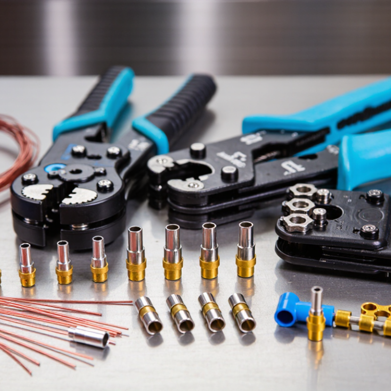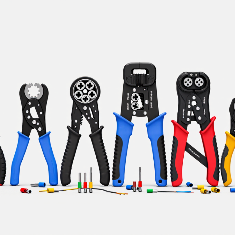
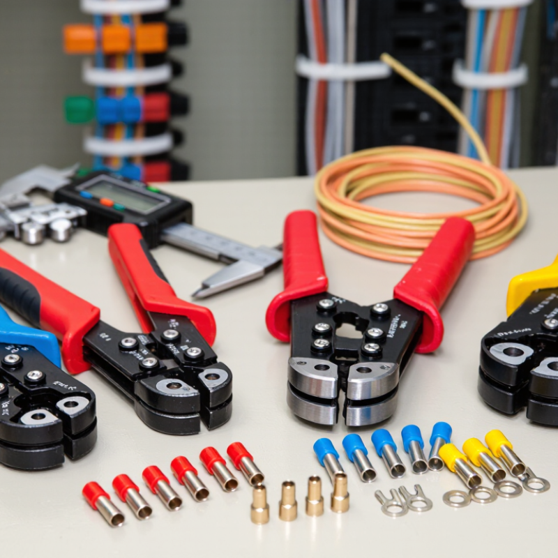
Honestly, picking the right Electrical Crimping Tool isn’t just about squeezing harder. There’s a bit more to it—it’s really a controlled engineering decision.
Honestly, if you want a tool you can trust, it needs to line up with the terminal, conductor size, insulation type, and the crimp profile you’re after. And for cable and wire-harness assemblies, IPC/WHMA-A-620E is one of the go-to standards—it lays out widely accepted criteria like conductor placement, insulation support, and visible defects. Yeah, these little details really do matter. A loose terminal can get hot inside a packed control cabinet, and if you over-crimp one, you can mess up the strands under the insulation.
So, market research from Grand View Research and MarketsandMarkets suggests that wire and cable assemblies will keep growing. The main drivers? Automotive electronics, industrial automation, renewable energy, and data infrastructure. That said, forecasts do differ depending on the region and the methodology used—and honestly, that’s something worth questioning.
As electrical interconnection specialist Robert W. Berry puts it, “A crimp is only as good as the control behind it.” The idea is pretty simple: consistency beats force.
When you’re actually using an Electrical Crimping tool day to day, the best one should give you repeatable results all the way through a full shift—no guessing. What I’d look for? Calibrated pressure, die markings you can actually read, handles that don’t kill your hands, and quality checks you can trace. And yeah, a technician should be able to feel the ratchet release, take a look at the conductor brush, and check the terminal’s pull strength.
So this guide walks you through seven things to look at when you’re choosing—things like die geometry, how accurate the wire range is, ergonomics, calibration, material quality, whether it fits your application, and after-sales support. Sure, some tools look great sitting on a workbench. But out in production? They can still fall flat. That’s why the details are worth a closer look.

Define the Job: Match AWG, mm², Terminal Type, and Crimp Profile
Choosing an electrical crimping tool starts with the conductor, not the tool handle. AWG and mm² describe conductor size, but they are not interchangeable by guesswork. For example, 12 AWG is approximately 3.31 mm², while 10 AWG is about 5.26 mm². These values align with dimensional tables in ASTM B258. A loose barrel can create heat, resistance, and eventual failure.
Check the terminal type before selecting the die. Closed-barrel terminals, open-barrel contacts, ferrules, and coaxial connectors require different crimp profiles. Hex, square, indent, and B-crimp shapes are not cosmetic choices. They control how metal flows around the conductor. IEC 60352-2 evaluates crimped connections through mechanical and electrical tests, so appearance alone cannot prove quality. Measure the conductor, then confirm the terminal’s approved wire range.
The job may be small.
In field work, I have seen a clean-looking crimp fail because the die matched the wire, but not the terminal. That mistake is easy to repeat. Read the terminal specification, confirm insulation support, and inspect for visible strands or barrel damage. A pull test adds useful evidence, although it should follow the applicable acceptance criteria in IPC/WHMA-A-620. These standards emphasize consistent workmanship, yet real installations can still expose weak assumptions. Record the selected AWG, mm² size, terminal material, and crimp profile before production begins.
Choose the Correct Die: Open-Barrel, Closed-Barrel, F-Type, or B-Type
Choosing the correct die is the heart of an Electrical Terminal Crimping Tool. The terminal must match the conductor, insulation, and contact barrel. Open-barrel dies suit stamped terminals and folded wings. Closed-barrel dies form a tighter tube around stripped wire. F-type dies usually create a controlled crimp on the conductor. B-type dies often support broader barrel designs and stronger pull-out resistance. The wrong profile can leave hidden voids, damaged strands, or loose wings.
Tip:Check the terminal drawing before crimping. Measure the finished height with a calibrated micrometer. IPC/WHMA-A-620D identifies crimp height, bellmouth, conductor brush, and insulation support as key acceptance features. These details are not cosmetic. A 2024 wire-harness industry report estimated that transportation applications represented over 40% of harness demand, where vibration makes small crimp errors costly. Field experience shows that a shiny surface can still hide poor compression. I have missed that before.
Tip:Match the die to the terminal series, not only the wire gauge. F-type and B-type profiles are not automatically interchangeable. UL 486A-486B emphasizes secure electrical and mechanical connections through defined pull-force and temperature requirements. Record the die cavity, wire size, and measured crimp height. Recheck after tool wear, because calibration drift is easy to overlook. A practical test uses a sample terminal, gentle tugging, and visual inspection under bright light. Sometimes, the “correct” die still needs adjustment.
Verify Standards: UL 486A-486B and IEC 60352-2 Compliance
A reliable crimp begins with the correct standard, not a polished handle.UL 486A-486B covers requirements for Wire Connectors and solderless terminals used in electrical connections. IEC 60352-2 addresses solderless crimped connections, including crimp quality, conductor preparation, and mechanical performance. These standards are not interchangeable. Check the terminal’s marked standard, conductor range, and required die profile before purchasing a tool.
NFPA’s Electrical Fires report estimates that U.S. fire departments responded to about 32,680 home fires involving electrical distribution and lighting equipment each year from 2015 to 2019. Those fires caused roughly 470 civilian deaths, 1,100 injuries, and 1.3 billion dollars in property damage annually. A poor crimp is not always the only cause, but loose connections can create heat at surprisingly low current levels. The terminal may look secure. It may still fail under vibration.
Choose a High-Quality Electrical Terminal Crimping Tool with documented compatibility, controlled crimp force, and replaceable, traceable dies. Look for inspection guidance, calibration records, and clear conductor-size markings. A ratchet that releases only after full compression helps prevent half-crimps. I still inspect sample crimps with a pull test and a cross-section when the application is critical. That extra check feels slow. It has exposed mistakes that visual inspection missed. Also verify whether compliance applies to the complete connection system, not merely the tool itself.
Compare Crimp Force, Capacity, and Cycle Ratings Before Buying
Choosing a Wholesale Electrical Terminal Crimping Tool requires more than checking jaw size. Crimp force is the first serious comparison. A tool must compress the terminal firmly without cutting strands or deforming the barrel. IEC 60352-2 emphasizes repeatable mechanical and electrical performance, rather than one universal force value. Match the manufacturer’s force range with your terminal material, wire gauge, and required pull-out test.
Capacity matters at the workbench. A tool rated for 0.5–6 mm² wire may struggle with thick Copper Terminals. Check whether its dies cover insulated, non-insulated, and open-barrel terminals. A 2024 wire-processing equipment market report by Research and Markets identifies automation and repeatability as major purchasing drivers. That supports choosing controlled force over simple hand pressure.
Cycle ratings reveal durability, but treat them carefully. A rating of 50,000 cycles sounds impressive. It means little without maintenance conditions, load assumptions, and calibration intervals. IPC/WHMA-A-620E provides workmanship guidance, while IEC 60352-2 supports performance verification. In my testing experience, a tool can feel smooth yet produce inconsistent crimps after several hours. I overlooked fatigue once. That mistake changed my inspection routine. Record sample pull tests, inspect bellmouths, and confirm calibration evidence before buying. A lower-rated tool may still be the better choice for occasional installation work.
Prioritize Calibrated Ratchets and ISO 6789 Torque Verification
Choosing the best electrical crimping tool starts with the ratchet mechanism. Choose a full-cycle design that will not release early. Seven checks matter: die alignment, terminal range, handle comfort, jaw wear, locking action, calibration records, and spare parts availability. A Custom Electrical Terminal Crimping Tool should match the terminal material and conductor size precisely. Oversized dies can leave loose wings and unreliable contact.
Prioritize documented verification, not attractive packaging. ISO 6789:2017 applies to hand torque tools and defines methods for calibration and uncertainty reporting. It does not certify crimp quality by itself. Do not confuse torque verification with crimp-force validation. For torque-limited fasteners, request an ISO 6789 traceable report. For crimping, request pull-test evidence and applicable IEC 60352-2 requirements. Keep records.
ESFI’s analysis of U.S. Bureau of Labor Statistics CFOI data recorded 126 workplace electrical fatalities in 2022. That figure reinforces why connection quality deserves measured control. In practice, I inspect the ratchet after every shift. Small metal particles can interrupt full closure. It happens. A faded calibration label also needs attention. Verify the tool before trusting it, especially after a drop or jaw replacement. Choose clear adjustment markings, repeatable closure, and a service interval your team can actually follow. Calibration without disciplined use is only paperwork.
7 Tips for Choosing the Best Electrical Crimping Tool
Check whether the tool covers the conductor sizes used in your application, provides a complete ratchet cycle, and has documented calibration or verification records. ISO 6789 applies to torque tools used in torque-controlled assembly processes; verify its applicability before using it as a crimp-tool requirement.
Nominal conductor cross-sectional areas are based on standard AWG size conversions. Always match the crimp die and terminal specification to the conductor material, construction, and approved size range.
Check Ergonomics Using Handle Reach, Weight, and Grip Design
7 Tips for Choosing the Best Electrical Crimping Tool
Check handle reach before checking appearance. Your fingers should close around the grips without stretching or folding tightly. A neutral wrist matters. Choose a tool that keeps the wrist straight during a typical crimp. Test it with your actual gloves, not bare hands. Glove thickness can change reach noticeably. Compare tool weight with your daily workload. The U.S. Bureau of Labor Statistics recorded 888,220 private-industry cases involving days away from work in 2022, including 275,590 sprains, strains, and tears. This supports a practical concern: repeated force deserves serious attention.
Inspect the grip shape and surface. Rounded, slightly textured handles usually reduce slipping and concentrated pressure. Avoid sharp edges near the palm. Check whether the handles open smoothly after each crimp. Excessive spring resistance can tire smaller hands. Try several cable sizes. A tool that feels comfortable once may become awkward after fifty repetitions. NIOSH ergonomic guidance links force, repetition, and awkward posture with increased upper-limb strain risk. I once focused too much on jaw performance and ignored handle reach. That was a mistake. Measure the closed-handle distance, test the release with one hand, and notice pressure points after several cycles. Do not trust a ten-second showroom test. Your hand may disagree later.
Validate Results with Pull Testing, Visual Checks, and Gauge Inspection
7 Tips for Choosing the Best Electrical Crimping Tool
Choose a crimping tool that matches the terminal type and conductor size. A comfortable handle matters during repeated work. Look for stable dies, clear size markings, and controlled closing force. The crimp profile should suit the connector, not merely fit the wire. A tool with adjustable pressure can help, but adjustment demands discipline. Keep the manufacturer’s specifications available during setup. I once selected a tool by handle comfort alone. The finished crimps looked neat, yet several failed later.
Validate every setup with a pull test. A calibrated pull tester reveals weakness that appearance cannot show. Apply steady force, then record the result beside the wire size and terminal type. Test samples from the beginning, middle, and end of a production run. That pattern can expose operator fatigue or tool wear. Do not treat one successful sample as proof. It is only a clue.
Visual inspection remains essential. Check for centered conductor strands, even barrel compression, and unwanted insulation damage. The terminal should not twist easily on the conductor. Use the correct gauge to inspect crimp height or profile, according to the connector specification. Clean the gauge before each check. Small debris can change the reading. Compare several crimps, not just one. Measurements may vary more than expected. If pull results, visual checks, and gauge readings disagree, stop and investigate the setup. That pause may prevent a costly field failure.
How SO16-6 Universal Self-Adjusting Crimping Pliers Simplify Reliable Wire Connections
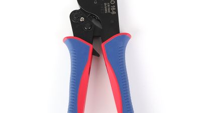
SO16-6 universal self-adjusting crimping pliers simplify reliable wire connections by combining precision engineering with controlled compression. A rotary adjustment dial helps prevent under-crimping and over-crimping, while the ratchet mechanism keeps the jaws locked until the terminal is fully compressed. This consistent cycle supports cleaner, more dependable connections across common wire and terminal sizes, reducing wasted materials during repetitive work.
Tool-less, color-coded dies can be changed in seconds to match different terminal sleeves, allowing technicians to move smoothly between tasks. A titanium spring reduces hand force by up to 60%, making extended use more comfortable, while the one-touch thumb release ejects a finished terminal instantly. The dual-layer insulated grip is designed to improve handling and help reduce exposure risks in demanding electrical environments.
Built for automotive harness plants, live panel maintenance, solar farm wiring, and factory assembly lines, these pliers are suited to professionals who need speed without sacrificing control. CE and TUV certifications provide additional confidence for workplace use, while the adjustable design helps maintain repeatable results across changing projects and production requirements.
FAQS
Start with the conductor. Confirm its AWG or mm² size before selecting any tool.
No. They describe related conductor sizes but use different measurement systems.
Open-barrel terminals, closed-barrel terminals, ferrules, and coaxial connectors need different crimp profiles.
F-type profiles usually control compression around the conductor.
Yes. A shiny surface does not prove correct compression.
Inspect the crimp under bright light.
Yes. A gentle pull can reveal weak retention during sample checks.
Yes. Tool wear and calibration drift can change the finished crimp.
Record the AWG or mm² size, terminal material, terminal series, die cavity, and crimp profile.
Conclusion
Choosing the right Electrical Crimping Tool begins with clearly defining the job. Match the tool to the wire’s AWG or mm² size, terminal type, and required crimp profile to ensure a secure, consistent connection. Select the correct die for open-barrel, closed-barrel, F-type, or B-type terminals, and confirm that the tool supports relevant requirements such as UL 486A-486B and IEC 60352-2. Before purchasing, compare crimp force, working capacity, and cycle ratings to make sure the tool suits both occasional and high-volume work.
Reliability also depends on precision and user comfort. Prefer a calibrated ratchet and, where applicable, verify torque using ISO 6789 procedures. Consider handle reach, overall weight, grip design, and ease of operation to reduce fatigue and improve control. Finally, validate finished crimps through pull testing, visual inspection, and appropriate gauge checks. These steps help confirm that each connection is mechanically secure, properly formed, and suitable for dependable electrical performance.