
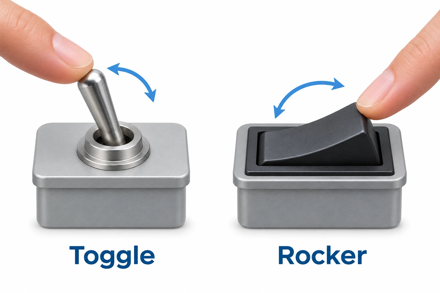
In a toggle switch vs rocker switch comparison, the visible difference is the actuator. A toggle uses a lever that moves between positions; a rocker uses a face that pivots when an end is pressed. Either description identifies how the user operates the control, rather than its complete electrical specification.
For an equipment panel, make three decisions separately: the required user action, the circuit function and the meaning of any indicator. Then confirm panel fit and application-specific ratings for the exact switch reference.
Toggle switch vs rocker switch: what the actuator tells you
The actuator is the part the operator touches. Its shape affects the available contact surface and the movement the operator makes. A lever-style control and a rocking face can therefore lead to different panel layouts even when the required circuit behavior is the same.
Evaluate the proposed actuator in the actual equipment layout. Check the user’s approach, nearby controls, labeling area and the space through which the actuator moves. Where gloves or restricted access matter, include those conditions in the component evaluation instead of assuming one style is always easier to operate.
Specify state retention and contact function independently
A momentary switch returns when the actuator is released. A maintained or latching switch retains its selected state until operated again. These behaviors need an explicit specification; the words “toggle” and “rocker” do not define them.
Poles and throws describe the contact configuration. Common designations include single-pole single-throw and single-pole double-throw, abbreviated SPST and SPDT. Record the required circuit function from the equipment design rather than inferring it from the number of visible actuator positions.
The terminal diagram is another necessary record. Similar-looking switches can leave the buyer with different circuit or terminal requirements. A photograph and an ON/OFF legend are insufficient instructions for connecting a replacement. Use the exact part’s circuit drawing and the equipment’s approved wiring documentation.
Compare the panel drawing before changing styles
A style change becomes practical only when the complete mounting arrangement fits. Compare the required cutout, panel thickness, body depth and terminal space on the selected drawings. The visible bezel is only one part of that fit check.
| Panel requirement | What to compare | What an appearance match leaves unresolved |
|---|---|---|
| Mounting | Cutout and permitted panel thickness | Whether the proposed switch mounts correctly |
| Front access | Actuator envelope and movement | Whether nearby controls or labels obstruct use |
| Rear clearance | Body, terminal and connection envelope | Whether the complete assembly fits behind the panel |
| Connection | Terminal drawing and required mating arrangement | Whether the existing connection can be retained |
For a replacement, retain the original panel and wiring requirements while comparing candidates. If the new switch requires a panel or connection change, treat that as an equipment-design change to review, rather than an interchangeable parts purchase.
Define what the indicator must communicate
Specify the indicator’s intended meaning before choosing an illuminated version. The operator may need to see a selected switch position, the availability of a supply or a separate equipment condition. Those are different requirements for the equipment designer to resolve.
The lamp specification and the switched-contact rating need separate checks. Request the indicator version, its supply requirements and the actual circuit arrangement together with the switch’s load specification. Do not assume the indicator supply is automatically the same as the switched circuit.
A lit actuator alone is not proof of the connected load’s state. The indication depends on the implemented circuit. Keep that distinction in the equipment specification, and avoid using a generic illuminated-switch photograph as evidence of how an indicator is wired.
What Gaopeng’s published rocker description establishes
Gaopeng’s LED illuminated ON/OFF rocker switch description identifies a black body, two positions and LED indication. Its selection instructions ask for the mounting cutout, available panel depth, terminal arrangement, switching function, supply voltage and circuit load.
Those published fields help identify the enquiry, but the exact version still needs confirmation. Request its drawing, electrical specification and indicator details for the intended equipment. The two-position description does not independently establish a pinout, a contact configuration or suitability for a particular load.
State environmental requirements separately and request the corresponding product documentation. An actuator style, body color or illuminated appearance does not establish a sealing rating or approval.
A replacement decision should preserve all three requirements
Consider an equipment designer evaluating a rocker in place of an existing toggle. The actuator preference is one decision. The required retained or momentary behavior and contact function are another. The intended indicator meaning is a third. A candidate must satisfy each applicable requirement before its appearance becomes a reason to select it.
The resulting parts record should identify the exact switch, panel drawing, circuit function, terminal drawing, load conditions and indicator version. Procurement can then request quantities for a defined component, while engineering can see which requirements would change with a proposed substitute.