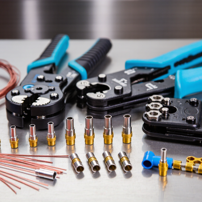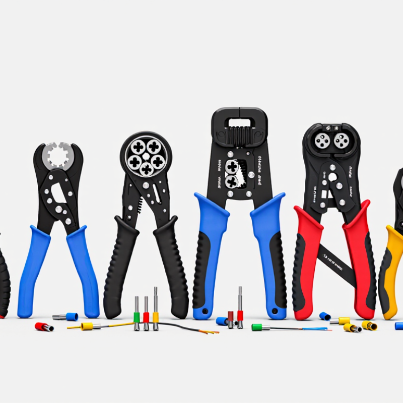
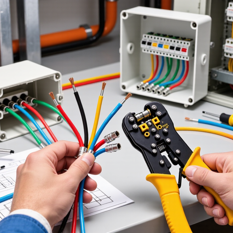
So, picking the right Splice Connectors? That can be the difference between a wiring job that holds up for years and one that gives up after a single rough season. A connector might look perfectly fine on the bench, then act up inside a vibrating machine or a damp junction box. What actually matters? Wire size, conductor material, insulation type, current rating, and where and how it is installed.
Most experienced electricians I know start with the cable details, not how shiny the connector looks. Check the wire gauge and the connector’s range against the manufacturer’s datasheet. Make sure it is rated for copper, aluminum, or whatever combination you are using. If it is going outdoors, look closely at sealing and how it handles moisture, heat, chemicals, and UV. In a control cabinet, space and temperature limits might matter more than waterproofing. Yep, small details turn into expensive headaches.
Installation quality counts just as much. A properly sized crimp should hold tight without crushing the conductor. A gentle pull test can catch a weak connection before you energize anything. Heat-shrink sleeves should cover all exposed areas, with no gaps near the cable entry. I have seen connections that looked neat enough but loosened up because the wrong tool was used. Easy mistake to make. Also easy to miss when you are rushing an inspection.
For reliable selection, follow recognized industry requirements and the connector manufacturer’s instructions. Independent testing can give you extra confidence, especially for high-current or safety-related work. But no connector can fix poor workmanship. Compare product evidence, site conditions, and long-term maintenance needs before buying. The “best” Splice Connectors are not always the priciest; they are the ones carefully matched to the real project.

Define the Purpose and Conditions of the Splice Connection
Choosing a splice connector starts with purpose, not package size. Decide whether the joint is permanent, serviceable, or temporary. Record conductor material, cross-sectional area, circuit voltage, expected current, and insulation type. A lighting repair has different demands from a motor feeder. The connector must match the conductor material and approved wire range. It should also meet a relevant standard, such as UL 486C or IEC 60998, where applicable.
The U.S. Fire Administration reports that 13.6% of residential building fires from 2014 to 2018. Poor connections are only one possible cause, but they deserve serious attention.
Then define the conditions around the splice. Is it inside a dry box, underground duct, rooftop tray, or vibrating machine?
Moisture, heat, chemicals, flexing, and limited space can change the choice. ESFI’s 2023 Workplace Electrical Safety Report lists 126 workplace electrical fatalities in 2020. A splice is small, but its failure can create larger system hazards.
SelecT connectors with documentedtemperature, voltage, pull-out, and ingress performance. Follow torque or crimp instructions exactly. I have seen a tight-looking joint fail after thermal cycling. Appearance can mislead.
Tips:
Leave enough conductor length for inspection.
Remove oxidation before joining.
Use a calibrated tool.
Seal exposed joints against moisture.
Photograph the finished splice.
Recheck it after the first load cycle.
If the environment is unclear, verify the specification. Guessing is cheaper only until failure.
Identify Compatible Wire Types, Sizes, and Materials
How to Choose the Right Splice Connectors for Your Project
Identify Compatible Wire Types, Sizes, and Materials
Choosing Wire Splice Connectors starts with identifying the conductors, not the connector color. Check whether the wires are solid, stranded, or finely stranded. Their construction changes how securely they grip.
Measure the conductor size in the installation guide or with a reliable wire gauge tool. Never rely on insulation thickness alone. Two wires may look similar but have different metal cross-sections. The connector must cover the complete size range of every joined wire.
Material compatibility also matters. Copper conductors usually require connectors rated for copper. Aluminum conductors need specifically approved connectors and suitable preparation. Mixing metals without proper compatibility can create corrosion, heat, and a weak connection. That mistake is easy to make.
I once rejected a connector after noticing one wire had unusually soft, compact strands. The package seemed suitable, but its listed range did not clearly include that construction. A small doubt deserves attention.
Check the connector’s voltage, current, temperature, and insulation ratings. These values should meet or exceed the circuit’s requirements. Also confirm whether the connector is intended for dry, damp, or outdoor locations.
Strip only the specified insulation length. Exposed conductor should not extend beyond the connector body. After installation, perform a gentle pull test and inspect for loose strands. Use the correct crimping tool when the connector requires one. A careful check takes seconds.
Installation conditions can change the choice. Tight spaces may need compact connectors, while vibration requires stronger mechanical retention. Follow the connector’s technical instructions and applicable electrical standards. Guessing is rarely efficient.
Compare Common Splice Connector Designs and Their Uses
Choosing splice connectors starts with the joint, not the package. In field repairs, I match the connector to wire gauge, conductor material, current, and exposure. A loose connector can heat under load. That small mistake becomes expensive.
Butt Splice Connectors join two wire ends in a straight line. They suit cable extensions and damaged-wire repairs. Crimp versions are fast and dependable when the terminal matches the wire size. I check every crimp with a gentle pull, then inspect for exposed strands. Heat-shrink sleeves improve moisture resistance, but they cannot repair a weak crimp.
Parallel splice connectors, also called tap or branch connectors, connect one wire to another without cutting the main conductor. They work well for lighting, sensors, and control circuits. Some designs pierce insulation, while others require stripping and clamping. Piercing types save time, yet vibration may weaken their contact. Soldered splice sleeves can create compact joints, but they require controlled heating and careful insulation. I once selected a connector by wire size alone and ignored the damp installation area. The joint worked initially, then developed corrosion. For outdoor or high-vibration projects, choose a connector with suitable sealing, strain relief, and temperature ratings. Use the correct crimp tool, follow the connector’s specifications, and test the finished circuit before closing the enclosure.
Evaluate Electrical Ratings, Insulation, and Environmental Protection
Choosing Crimp Splice Connectors starts with the circuit’s real electrical demands. Check voltage, continuous current, conductor size, and short-circuit conditions. Do not rely only on package claims. UL 486C covers wire connectors used in insulated and uninsulated applications, while IEC 60998 addresses connecting devices for household and similar fixed installations. These standards help, but installation quality still matters. A loose crimp can create heat beneath an apparently perfect sleeve.
Insulation must match the working environment. PVC may suit dry indoor panels, while heat-shrink insulation offers stronger sealing against moisture and vibration. For outdoor or wet locations, review the enclosure’s IP rating under IEC 60529. IP65 resists dust and water jets, but it does not guarantee immersion protection. NFPA’s Electrical Fires report estimates that electrical distribution and lighting equipment caused about 35,150 U.S. home fires annually from 2015 to 2019. That figure makes thermal performance worth checking carefully. I have seen connectors pass a basic continuity test, then discolor near a high-load terminal. Testing only once is not enough.
Tips: Confirm the conductor material and diameter before crimping. Use the specified die, then inspect the crimp barrel for distortion. Add a pull test. In corrosive areas, select sealed connectors and provide strain relief. Record the crimp tool and inspection result. Small records prevent large guesses. Recheck the choice if temperature, moisture, or vibration changes. A perfect rating on paper can still fail in a poorly supported cable.
| Connector Type | Typical Conductor Compatibility | Typical Voltage Rating | Typical Current Capability | Insulation and Temperature Considerations | Environmental Protection | Suitable Applications |
|---|---|---|---|---|---|---|
| Twist-On Wire Connector | Two or more solid or stranded copper conductors of compatible sizes; commonly used with small building-wire conductors. | Generally up to 600 V in listed wiring applications. | Depends on the conductor size, connection quality, and product listing; it does not increase the ampacity of the conductors. | Use only with conductors and insulation types permitted by the connector instructions. Many versions are intended for ordinary indoor temperature ranges. | Normally intended for dry, protected locations unless specifically listed for damp or wet environments. | Indoor branch-circuit splices, lighting circuits, junction boxes, and routine maintenance work. |
| Crimp Butt Splice | Usually joins two wires of the same or compatible cross-sectional area; available for insulated and non-insulated crimping systems. | Commonly 300 V to 600 V, depending on construction and listing. | Must be matched to the conductor gauge and installed with the correct crimp profile and tool. | Vinyl, nylon, or heat-shrink insulation may be available. Heat-shrink versions provide improved sealing after proper heating. | Standard insulated versions suit dry areas; adhesive-lined heat-shrink versions are better for vibration, moisture, and corrosion exposure. | Automotive wiring, control panels, equipment repairs, and cable extensions where a compact inline joint is required. |
| Lever-Actuated Compact Connector | Often accepts solid, stranded, and fine-stranded copper conductors within the specified size range. | Commonly rated up to 450 V or 600 V, depending on the listed model and application. | Typically suitable for low- to medium-current circuits within the specified conductor range; verify the exact rating before use. | Insulated housing provides touch protection. Confirm allowable operating temperature, conductor type, and wire-strip length. | Generally intended for dry indoor enclosures; additional enclosure protection is required in damp or outdoor locations. | Lighting, residential wiring, control systems, and applications requiring easy inspection or later disconnection. |
| Insulation-Piercing Connector | Designed for compatible insulated cables without fully removing the insulation; conductor diameter and insulation thickness are critical. | Often available for low-voltage systems, commonly below 1000 V; the exact listing controls. | Varies widely by design and cable size. The connector must be selected for the conductor material, diameter, and current load. | Sealed or gel-filled designs can protect the piercing interface. Do not use where the connector is not approved for the cable insulation. | Some versions provide moisture-resistant or weather-resistant sealing for outdoor low-voltage installations. | Outdoor lighting, telecommunications, control wiring, and installations where stripping insulation is undesirable. |
| Mechanical Set-Screw Connector | Suitable for larger solid or stranded conductors, including certain copper-to-copper or copper-to-aluminum combinations when specifically listed. | Commonly 600 V; some designs are listed for higher-voltage equipment applications. | Can support high-current feeders when correctly sized, torqued, and installed according to the product instructions. | Usually supplied with an insulating cover or installed inside an approved enclosure. Temperature rating must match the conductor insulation and equipment. | Requires an enclosure suitable for the location. Anti-oxidant compound or joint preparation may be required for certain conductor materials. | Distribution equipment, feeder splices, service equipment, industrial panels, and larger conductor transitions. |
| Heat-Shrink Solder Sleeve | Best for compatible small-gauge wires where the solder band, conductor size, and insulation diameter match the sleeve. | Often rated for low-voltage applications; verify the individual listing before use on mains wiring. | Generally intended for low- to moderate-current circuits and depends on the conductor size and solder joint quality. | Heat-shrink insulation provides electrical isolation and strain relief. Installation requires controlled heating to avoid damaging insulation. | Adhesive-lined versions can provide a sealed joint with improved resistance to moisture, dust, and vibration. | Electronics, instrumentation, marine low-voltage wiring, sensor cables, and compact harness repairs. |
| Gel-Filled Waterproof Splice | Available for compatible copper conductors and cable sizes specified by the connector manufacturer. | Commonly used in low-voltage systems; voltage limits vary substantially by construction. | Must be selected according to conductor size and the continuous current of the circuit. | Gel or encapsulant helps protect the electrical interface, but it does not compensate for an undersized conductor or poor connection. | Designed for wet, buried, underground, or exposed locations when the complete assembly is listed for that environment. | Landscape lighting, irrigation controls, outdoor sensors, underground low-voltage wiring, and garden equipment. |
Choose the Correct Installation Method and Required Tools
Choosing the Correct Installation Method and Required Tools
Selecting Marine Splice Connectors starts with the installation environment. Saltwater, vibration, moisture, and limited working space can change the correct method. A sealed crimp connection often suits exposed marine wiring because it creates a firm mechanical joint. Solder-seal methods may work for specific low-stress applications, but they require careful heat control. Follow the connector’s rated wire size and environmental instructions.
Use a calibrated ratcheting crimper for consistent pressure. Ordinary pliers can deform the sleeve unevenly. You may also need a wire stripper, cable cutter, heat gun, inspection light, and a multimeter. Keep the heat gun moving. Concentrated heat can damage insulation or shrink tubing. Before crimping, remove only the required insulation length. Exposed copper should not extend beyond the connector barrel.
Preparation decides reliability. Clean, dry cable ends matter. Check that the conductor is fully inserted before making the connection. After installation, inspect the seal for complete shrinkage and test continuity with a multimeter. Gently pull each wire. It should not move.
I still recheck every connection near bilge areas. One missed seal can invite corrosion. A perfect-looking joint may still fail under vibration. For that reason, protect the splice from sharp edges and avoid bending it immediately after installation. The correct tool is helpful, but careful observation matters more.
Verify Connection Quality, Safety, and Long-Term Reliability
Choosing splice connectors starts with the cable, not the package. Confirm conductor material, size range, insulation diameter, current rating, and installation environment. A connector made for copper may not suit aluminum conductors. Check technical data and applicable electrical standards before ordering. In damp, vibrating, or high-temperature locations, select a connector rated for those conditions. Small mismatches become serious faults.
Connection quality depends on preparation. Strip only the specified length, keeping strands straight and clean. Insert the conductor fully, then apply the stated torque when required. I usually mark the insulation edge before insertion and perform a gentle pull test afterward. The wire should not move, and no bare conductor should remain exposed. A transparent housing can reveal incomplete insertion, but it cannot prove a sound connection. I once trusted a neat-looking joint too quickly. Rechecking exposed a shallow insertion.
Safety also requires mechanical protection. Keep the splice inside an approved enclosure, away from sharp edges, heat sources, and standing water. Use strain relief where cables may flex. Inspect the joint after installation and during scheduled maintenance. Look for discoloration, looseness, cracked insulation, or moisture marks. Record the connector type, conductor size, torque value, and inspection date. These records support consistent work and simplify failure investigations. Do not rely on appearance alone. A connection can look perfect and still overheat under load.
T Tap Wire Connectors: Applications and Market Outlook—Insights from Grand View Research’s Electrical Connectors Report
T-tap wire connectors are increasingly used in automotive electronics, industrial controls, lighting systems, and low-voltage equipment because they enable fast circuit branching without cutting the original conductor. Grand View Research’s *Electrical Connectors Market* report places the global market at approximately USD 84 billion in 2022 and projects growth of about 5.6% annually through 2030, supported by vehicle electrification, factory automation, and expanding electronic content. These trends are increasing demand for compact, reliable connection methods that reduce installation time and wiring errors.
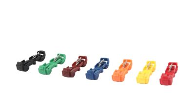
A self-stripping T-tap connector can pierce insulation with precision stainless-steel blades, eliminating manual wire stripping and potentially saving around 10 minutes per connection. Its three-layer construction—nylon outer shell, PVC barrier, and copper-alloy core—supports operation from -40°C to 105°C while resisting oil and gasoline. A spring-loaded tension clamp maintains more than 15 N of pull force and is designed to withstand 20G vibration, making it suitable for engine bays and mobile equipment. Color coding further simplifies installation: red supports 22–18 AWG, blue 18–16 AWG, and yellow 16–14 AWG, helping technicians match wire gauges quickly and consistently.
FAQS
They join two wire ends in a straight line. They suit cable extensions and damaged-wire repairs. Match the connector to wire size.
They connect a branch wire without cutting the main conductor. They suit lighting, sensors, and control circuits. Neat and practical.
No. They save installation time, but vibration can weaken contact. Use sealed, clamped designs for exposed or high-vibration areas.
A sealed crimp often provides a firm mechanical joint. It can resist moisture when installed correctly. Solder-seal methods need careful heat control.
Use a calibrated ratcheting crimper, wire stripper, cable cutter, heat gun, inspection light, and multimeter. Ordinary pliers may deform the sleeve.
Keep cable ends clean and dry. Remove only the required insulation length. Insert the conductor fully. Exposed copper should not pass the barrel.
Inspect the crimp and seal carefully. Pull each wire gently. Test continuity with a multimeter. The wire should not move.
No. Heat-shrink improves moisture resistance, but it cannot repair poor mechanical contact. Rework the connection instead.
I once selected a connector by wire size alone. I ignored a damp installation area. The joint worked initially, then corrosion appeared.
Keep it away from sharp edges. Avoid bending it immediately. Protect it from vibration and provide suitable strain relief. Small details matter.
Conclusion
Choosing the right Splice Connectors begins with understanding the purpose and conditions of the connection. Consider whether the splice will be used for temporary repairs, permanent wiring, indoor systems, outdoor equipment, or areas exposed to moisture, heat, vibration, or chemicals. Confirm that the connector is compatible with the wire type, conductor material, wire gauge, insulation, and number of conductors involved. Different designs, such as crimp, twist-on, push-in, or screw-based connectors, serve different installation needs and levels of mechanical stability.
Before making a selection, review the connector’s voltage and current ratings, insulation performance, temperature range, and environmental protection. Choose an installation method that matches the connector design and prepare the required tools, such as strippers, crimpers, or torque-controlled drivers. After installation, inspect the splice for secure conductor placement, proper insulation coverage, and adequate strain relief. Testing continuity, checking for unwanted resistance, and protecting the connection from environmental stress will help ensure safe performance and long-term reliability.